Computer Network Tutorial

Introduction of Computer Network Types of Computer Network Network Topology Computer Networking Architecture Transmission Modes (Data Flow) Basic Networking Devices Integrate Services Digital Network (ISDN)

Model

OSI Model TCP/IP Model

Physical Layer

Digital Transmission Analog Transmission Transmission Media Switching

Data Link Layer

Error detection and Error correction Data Link Control Multiple Access Aloha

Network Layer

Network Layer - Logical Address Address Mapping Unicast Routing Protocol

Transport Layer

Process to Process Delivery User Datagram Protocol Transmission Control Protocol Stream Control Transmission Protocol Session Layer and Presentation Layer

Application Layer

Domain Name System Application Protocol E-mail Cryptography

Misc

Classes of Routing Protocols Classification of Routing Algorithms Controlled Access Protocols in Computer Networks Differences between IPv4 and IPv6 Fixed and Flooding Routing Algorithms Advantages and Disadvantages of Fibre Optics Cable APIPA Difference between Active and Passive FTP Fiber Optics and its Types Method of Joining and Fusion of Fiber Optic Cable Define Framing in Computer Network Disadvantages of Computer Network Mesh Topology Diagram in Computer Network Ring Topology in Computer Network Star Topology in Computer Networks 4G Mobile Communication Technology Advantages and Disadvantages of LAN Advantages and Disadvantages of MAN Advantages and Disadvantages of WAN Application Layer in OSI Model Cyclic Redundancy Check Example Data link layer in OSI model Difference between Transport and Network Layer Hamming Code Example Network Layer in OSI Model Session Layer in OSI Model Transport Layer in OSI Model Two Port Network in Computer Networks Uses of Computer Networks What is Computer Network What is Framing in a Computer Network Advantages and Disadvantages of Bus Topology Difference between Star Topology and Bus Topology Subnetting in Computer Network Subnetting Questions and Answers What is Bus Topology What is Network Topology and Types in Computer Networks Access Control in Networking Basic Characteristics of Computer Network Benefits of SOCKS5 Proxy in Computer Networks Computer Network viva Questions Difference between BOOTP and RARP Difference Between Network Topologies and Network Protocols Difference between NFC and RFID Difference Between Point-to-Point Link and star Topology Network Differences Between MSS and MTU Differences Between Trunk Port and Access Port Different Modes of Communication in Computer Networks MIME Protocol in Computer Networks Modes of Communication in Computer Networks Network Attack in Computer Network Port Address in Networking Simplest Protocol in Computer Network Sliding Window Protocol in Computer Network Stop And Wait Protocol in Computer Networks TCP 3-Way Handshake Process in Computer Networks What is a Proxy Server What is APPN What is ICMP Protocol What is Point-to-Point Protocol What is Port Address in Networking What is the HDLC Protocol What is VRRP Protocol Difference Between Analog and Digital Signals Difference Between Hub and Repeater Difference between Repeater and Switch Difference Between Transparent Bridge and Source Routing Bridge Source Routing Bridge in Computer Networks Transparent Bridge in Computer Networks Transport Protocol in Computer Networks Types of CSMA in Computer Networks What is Wired and Wireless Networking Network Security in Computer Network Disadvantages of Extranet Difference Between TELNET and FTP Define Protocol in Computer Networks Guided Transmission Media in Computer Network What is a Gateway in a Computer Network IGMP in Computer Networks LAN Protocols in Computer Networks MAN Meaning in Computer Modulation Techniques in Computer Networks Switching in DCN TCP/IP Applications What is IGMP? What is Modem in Networking What is Non-Persistent CSMA Difference between Cell Splitting and Cell Sectoring Forouzen Computer Network Open Loop and Closed Loop Congestion Control Types of Cluster Computing WAP-Wireless Access Point What are the elements of the Transport Protocol Difference between Gateway and Switch Flow Control in Data Link Layer Body Area Network Flooding in Computer Network Token Ring in Computer Networks VoIP in Computer Networks What is Infrared Transmission Congestion Control Techniques Forward Error Correction (FEC) Switching Techniques What is Telnet in Computer Network

Method of Joining and Fusion of Fiber Optic Cable

What is Fiber Optics Cable?

Fiber optics cable transforms the information at a light pulse. We can transfer voice, data, and video through the fiber optics cable. The fiber optics cable consists of a glass core and glass core coated with Kevlar membranes to provide strength to the fiber optics cable. This cable can be connected with the necessary physical connection. 

Operating Principle

The fiber optics cable has optical fiber. This optical fiber carries the light and allows the information to transfer in the form of light. These fibers consist of a core and a protective layer, and due to the phenomenon of total internal reflection, the data can be transmitted in the form of light through the fiber optics cable. Every fiber optics cable has an individual coated fiber, and every individual coated fiber has the resin buffer layer and core tube. Sometimes we may use dark and light-absorbing material only to prevent the cross-talk between the wires. This method prevents data leakage from the fiber. Several protective layers, when added with a glass core, then a fiber optics cable can be formed. 
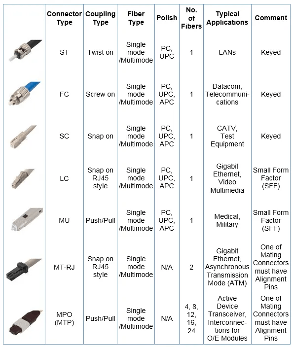
Connectors

The following table gives sufficient information about the connectors:

Method of Joining and Fusion of Fiber Optic Cable

Joining Fiber Optics Cable

There are two methods available for the joining of the fiber optics cable. These two methods are mechanical splicing and fusion splicing. Here, the permanent connection between two fiber optic cables is known as splicing. Typically we can choose one splicing over another splicing due to economics. The fusion splicing is lower per connection, whereas the initial investment has higher per connection. Mechanical splicing is a type of alignment device. It is specially designed to hold the two fiber ends so that the light can pass from one end to another end. During the joining process of optical fiber, the main thing is the core of the cable is perfectly aligned with each other. During the alignment, the amount of light lost some data. If we do not align the cable properly, then part of some light gets lost during the transmission process. 

Four leading causes of optical loss

  1. Poor core alignment: The poor alignment of the fiber optics cable occurred due to the optical connector loss.
  2. Axial run out: An optical loss of a connector occurred due to the improper cutting of the optics cable during the joining of the two wires. To avoid this axial run out, we have to increase the angle of cutting during the joining of the two wires. 
  3. Gap: The gap between the optical fiber also causes the optical loss of the connectors. For example, if the connection between the face and the optical fibers is not correctly aligned, then the loss of connection results due to the air gap between the fibers. The end of the gap between optical fibers results in 0.6dB due to the change in the refractive index of cable and wire. 
  4. Reflection: The end of the optical fiber should be well polished so that we can minimize data loss during the transmission. A rough surface can emit more light during the transmission of the data since the fiber optics cable is very small, so that an unpolished surface can emit more scattering of light. Cleaning the end of the optical line is very important for merging two cables. 

Fusion Splicing

Fusion splicing involves joining two optical fibers end-to-end using some source of heat.

The result is fusing the two fibers so that light passing through the fibers is not scattered or reflected by the splice and so that the splice and the region surrounding it are almost as strong as the virgin fiber itself.

This produces a continuous connection between the fibers enabling deficient loss of light transmission. The heat source is usually an electric arc, but it can also be a laser, gas flame, or a tungsten filament through which current is passed.

Fusion splicing is the most widely used method, providing the lowest loss and negligible reflectance and the most robust and reliable joint between two fibers.