Two Port Network in Computer Networks
A Two Port Network is a four-terminal electric network or circuit with 2 terminals on both sides, each connecting with more circuits or devices. Two terminals together make a port, one port is used as an input port from which current is supplied, and the other port is used as an output port which emerges the same energy. The first is called port1, and the second port is called port2.
Ports -
1. One port network
It is an electric network that contains two terminals to form a port, in which current enters from one terminal and leaves through another terminal. Examples of one-port networks can be Resistors, Inductors, and Capacitors. Each of them works on 2 terminals.
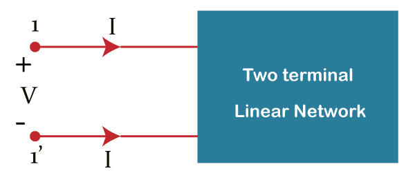
The above figure is a one-port network circuit in which 1 and 1' represents a port. It has one port only as one port network has two terminals, i.e., one port.
2. Two port Network
It is the same as one port network, but contains a pair of two terminal electrical networks through which current is passed from one terminal and leaves from another end or terminal of each port.
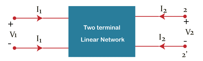
The above figure depicts two port networks, which contain 4 terminals, one pair of terminals, 1 & 1’ represents one port known as port1, and the other pair of terminals, 2 & 2', represents another known port as port2.
The circuits in two port networks consist of four variables, namely- V1, V2, I1, and I2, as shown in the above figure, where two variables are chosen as independent variables and the other two as dependent variables.
V1 - represents the voltage across port1
I1 - shows current into port 1
v2 - represents the voltage across port2
I2 - shows current into port 2
There are 6 possible equations representing a dependent variable in terms of independent variables. The coefficients of independent variables are called parameters.
Two Port Network Parameters
There are certain parameters of two port network called two port network parameters or two port parameters. There are several types of two port network parameters. The list below is some of the calculative parameters of two port network:
- Z parameters
- Y parameters
- T parameters
- T’ parameters
- h parameters
- g parameters
- S parameters
Z parameters
Z parameters are also known as Impedance parameters because they are simply the ratio between voltage and current. There are 2 equations to solve the Z parameter by considering the variables V1 and V2 as dependent variables and I1 & I2 as independent variables.

Where,
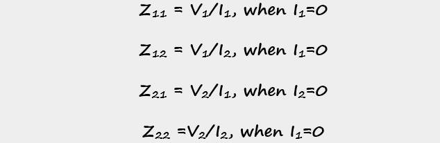
The unit or dimension of the Z perimeter is Ohm(O). Z parameters are also called open-circuit impedance parameters because parameters can be solved by doing open circuit operations on the ports. By doing an open circuit of port1 and port2, user can calculate Z parameters, Z11 & Z21 and Z22 & Z12 respectively.
Y parameters
Y parameters are also known as admittance parameters because they are the ratio between current and voltage. There are 2 equations to solve the Y parameter by considering the variables V1 and V2 as independent variables, and I1 & I2 as dependent variables. Parameters of Y are the coefficients of independent variables that are V1 and V2.

The Y parameters are

The measuring unit of Y parameters is mho.
These are also known as short-circuit admittance parameters because Y parameters can be solved with the help of short circuit of the ports. By doing a short circuit of port2 and port1, user can calculate Y parameters, Y11 & Y21 and Y22 & Y12 respectively.
T parameters
T parameters are mostly known as ABCD parameters or Transmission parameters. There are 2 equations to solve the T parameter by considering the variables V1 and I1 as dependent variables and V2 & I2 as independent variables. The T Parameters are the coefficients of V2 and -I2.

The T parameters are
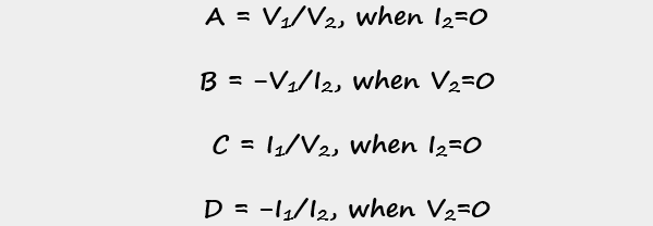
A and D parameters do not have any measuring units as both of those are dimension less. The measuring units of parameters B and C are ohm and mho respectively.
A and C parameters can be calculated by doing an open circuit of port 2. Similarly, B and D parameters can be calculated using an open circuit of port 2.
T ’ parameters
T’ parameters or A’B’C’D’ parameters are also known as inverse transmission parameters. There are 2 equations to solve the T parameter by considering the variables V2 and I2 as dependent variables, and V1 & I1 as independent variables. A’B’C’D’, the coefficients of V1 and -I1 are the T parameters

The T’ parameters are
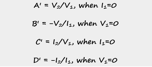
A’ and D’ parameters do not have any measuring units because both of those are dimension less. The other parameters B’ and C', have units that are Ohm and Mho, respectively.
By doing open circuit of port 1, the parameters, A’ and C’ can be calculated. With same way, the other two parameters, B' and D', can be calculated.
h-parameters
These parameters are also known as hybrid parameters. This parameters can be used in transistor modeling circuits or networks.
There are 2 equations to solve the h parameter by considering the variables V1 and I2 as dependent variables and I1 & V2 as independent variables. Coefficients of I1 and V2 are the h parameters.

The h parameters are
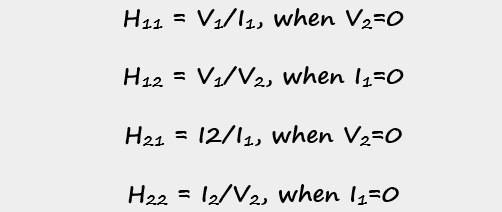
h12 and h21 parameters do not have any measuring units because both of those are dimension less. The other parameters, h11 and h22, have units that are Ohm and Mho, respectively.
The parameters h11 and h21 can be calculated using an open circuit of port 2. Similarly, the other two parameters, h12 and h22, can be calculated using a short circuit of port1.
g-parameters
These are also known as inverse hybrid parameters. There are 2 equations to solve the g parameter by considering the variables I1 and V2 as dependent variables and V1 & I2 as independent variables. The coefficients, V1 and I2 are the parameters of g.
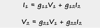
The g parameters are
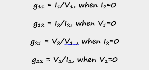
g12 and g21 parameters do not have any measuring units because both of those are dimension less. The other parameters, g11 and g22, have mho and ohm units, respectively.
g-parameters can be calculated by doing open circuit of port2 of the parameters g11 and g21. And by doing short circuit of port1 of, the other two parameters, g12 and g22.
S-parameters
S-parameters are also called scattering parameters. It is different form all other ports and parameters. All other parameters are calculated on voltage and current but are based on the incident and reflected waves. There are 2 equations to solve the g parameter by where the ak{\displaystyle \scriptstyle a_{k}}a are the incident waves and the bk{\displaystyle \scriptstyle b_{k}} are the reflected waves at port k. The coefficients of variables a and b are called s-parameters.
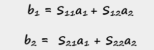
The s-parameters are
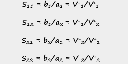
Where 2 port S depicts the following description:
S11 shows the input reflection of port voltage.
S12 shows the reverse of voltage gain.
S22 is the forward voltage gain.
S22,{\displaystyle S_{22}\,} represents the output reflection of port voltage.