What is Framing in a Computer Network?
In the stream of bits, the data is stored by transmitting the bit by the connection of two devices through cable. This type of connection for data transmission is called framing. These bits, however, must be organized into identifiable information blocks. The data connection layer controls framing.
The data transmission in the physical layer is a synchronized transfer of bits, which transmits from the source to the destination. This section will concentrate on data transmission between two devices using point-to-point links. Once the network layer gets its packet, the source and destination addresses are added to them by the data link. The data connection layer converts them to frames. A packet is separated into a tiny frame when the frame size becomes too large. These smaller-sized frames allow more efficient error management and flow control.
Framing in a Computer Network

Let's look at the diagram to see how this works.
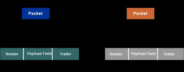
We provided two gadgets, each with an adapter attached. This adapter will convert the data into signals that will be transmitted across the cable and received by the physical layer of other devices.
In a computer network, frames are used to deliver and receive data. In the data connection layer, bits are arranged in the form of frames that can be differentiated from one another.
The data connection layer wraps a packet in a frame with a header and a trailer for transmission via local media.
In telecommunications, a frame is defined as data that flows between network locations.
The frame is also known as the combination of the trailer field and header field. These frames stores the information and move the data bit by bit in the serial process. Only the data connection layer understands these frames.
The frames can be obtained from the following components:
- Frame Header: In the frame header, addresses of the source and destination is stored.
- Payload field:- In the payload field, the message stored is about to send.
- Flag:- The flag indicates the beginning and finish of the frame.
- Trailer:- The trailer provides mistake detection and repair information.
The physical layer has no knowledge of the frames. Before transferring them, it turns individual bits into comparable signals. The physical layer of the receiving device must turn these bits into frames, but several issues must be addressed first.
Challenges in Framing:-
Suppose the transmitting device delivers 100 bits of data, 50 of which are of frame one. All of the bits are received by the receiving device. How will the receiver know that the frame contains up to 50 bits?
Before commencing communication and data sharing, several protocols are specified between the devices. Let both devices agree that the start and end of the frame will be 11011 which is added with the header and trailer. The receiving device will get a frame that looks like this: 1101101101101011011.
If you look closely, you will see another issue, the frame that was received contains a section that mimics the start and finish of frame 1101101101101011011. As a result, the receiver will only regard these bits 1101101011011, i.e., the preceding component will not be considered a part of the frame. This is also taken as or identified as Framing Error. To comprehend the answers to this dilemma, we must first understand the various forms of Framing.
Types of Framing in a Computer Network
1. Fixed-size Framing:-
With this type of sort of Framing, the frame length gives the delimiter of the frame because the size of the frame is constant.
This Framing does not require additional boundary bits to identify the start and end of the frame. For example, if a device sends 200 bits of data and the frame size is fixed at 50 bits, the receiver will instantly know that the following 50 bits are of frame two, and so on.
The disadvantage of this framing is that internal fragmentation occurs when the data size is smaller than the frame size. The padding might help you prevent this problem.
2. Variable size framing:-
Due to the reason that each frame that is sent can change, therefore some extra devices are also necessary to assist the end of one frame and the start of another frame.
For example, out of 200 bits of data, 100 bits may represent frame 1, 25 bits may constitute frame 2, and the remaining bits may constitute frame 3.
In variable-size Framing, the following two methods are used to determine the frame delimiters, i.e., the start and end of the frame:
Approaches to Framing in Computer Networks:-
- Bit-Oriented Framing
- Byte-Oriented Framing
- Clock Based Framing
Bit-oriented Framing:-
It considers the frames to be a collection of bits. In the higher layer, data is delivered as a series of bits that may be interpreted as text and multimedia data.
Bit-oriented protocol:-
High-Level Data Connection Control (HDLC) is a protocol for the data link layer. The frame format is described in the picture below, along with the bits.
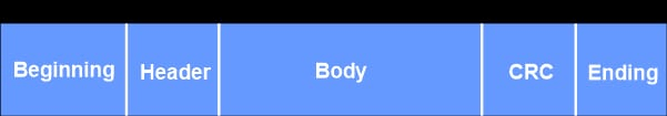
Beginning and Ending Sequence: In this protocol, the 8 bits inserted at the start and end of the frame are 01111110. When the connection is idle, these bits are also broadcast to synchronize the clock.
CRC, which is also known as cyclic redundancy check, is useful for identifying mistakes.
We may now return to our prior consideration of the Framing Error issue. Bit-Stuffing is the answer to this problem.
Let's look at an example using the HDLC protocol to see how it overcomes this difficulty.
If you observe that this frame has a component identical to the beginning in its body, consider the frame to be sent and received by the devices to be 011111100101000111111001111110. Bit Stuffing involves inserting a pattern of arbitrary length bits into the message to distinguish it from the delimiter.
As a result, anytime the sender device detects a frame with five consecutive 1's, it will insert a '0' bit. The format will be 0111111001010001111101001111110. When the receiving device receives this frame and comes across a '0' after five consecutive bits, it removes it to preserve the original frame.
Byte-oriented Framing:-
The frames are reported as a collection of bytes (8 bits), often known as a character, and therefore the term Character Oriented Approach.
Byte-Oriented Protocols are classified into three types:
- Binary Synchronous Communication Protocol (BISYNC)
- Digital Data Communication Message Protocol (DDCMP)
- Point-to-Point Protocol(PPP).
Binary Synchronous Communication protocol (BISYNC):-
It's a sentinel strategy. The defined frame format, as well as the bits, are shown in the image below.
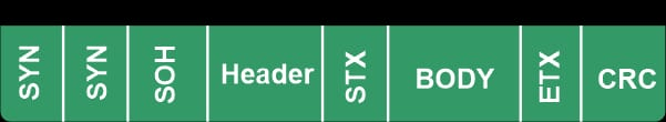
SYN: A unique beginning character.
SOH: Beginning of the Header.
STX: The beginning of the text.
ETX: The end of the text.
The STX and ETX protect the portion's data. We invented Byte Stuffing to avoid the framing error problem in this technique. When the frames include characters, this is utilized. The byte is inserted in it to differentiate the message from the delimiter.
Point-to-Point Protocol (PPP):-
It is a wide-area network protocol that operates via internet connections. This protocol is primarily used in high-speed, heavy-load broadband communication. The frame format is described in the picture below, along with the bits.
The flag's bit pattern is 01111110.
In the event of a broadcast, the address field is set to 11111111.
The control value is set to 11000000 as a constant.
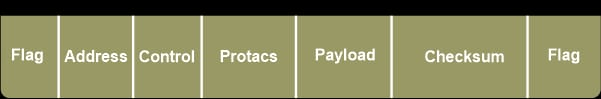
The protocol is made up of one or two bytes that specify the kind of data in the payload portion.
The data is carried by the payload. This field can have a maximum length of 1500 bytes.
The error can be detected by using the checksum field.
If the flag bits exist in the payload component, the problem is overcome via character/byte stuffing, as in the preceding examples.
Digital Data Communication Message Protocol (DDCMP):-
The new count field is required for this protocol. The frame format is described in the picture below, along with the bits.
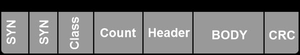
The main disadvantage of this strategy is that if a transmission fault corrupts the count field, the end of the frame will not be appropriately identified by the receiver.
Clock-based Framing:-
This Framing is mostly utilized in optical networks like SONET. A sequence of repeating pulses maintains a steady bit rate and keeps the digital bits aligned in the data stream in this manner.
Advantages of Framing in Data Link Layer:-
- In the process of time-division multiplexing, frames are utilized continuously.
- It makes easier for a sender to convey a collection of valid bits to a receiver.
- Frames also include headers that contain information like error-checking codes.
- Frame structures are used in frame relay, token ring, ethernet, and other data connection layer approach.
- Frames allow data to be partitioned into several recoverable portions that can be examined for corruption.
- It has a flow management system that regulates frame flow to prevent data congestion on slow receivers caused by rapid senders.
- It provides dependable data transmission services between peer network levels.