Digital Transmission
Line Coding
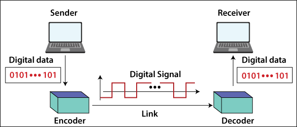
Digital signal is converted in the digital data that process is known as the Line Coding. That data is stored in the computer in the form of text, audio, video, numbers, and graphical images as the sequence bits. In the line coding, the sequence of bits is converted into the digital signal. Digital data is converted into a digital signal at the sender. Digital data is retrieved by decoding the digital signal at the receiver. There are shows in the figure below.
Line coding schemes
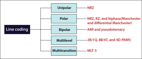
Line coding schemes are divided into five different types:
1. Unipolar
2. Polar
3. Bipolar
4. Multilevel
5. Multitransition
Unipolar Scheme
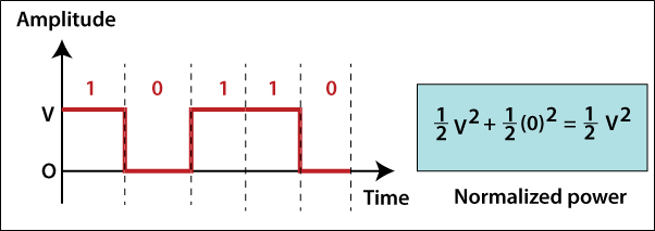
In this scheme, all signal levels occur on one side of the time-axis, either up or down.
NRZ (Non-Return to Zero): The unipolar scheme was mainly designed to non-return-to-zero (NRZ) in which 1 bit defines the +ve voltage, and 0 bit defines the zero voltage. The unipolar scheme NRZ shows in the diagram below.
Polar Scheme
In this scheme, the voltages occur on both sides of the time axis. For example, If the voltage level is 0 (zero), it can be positive, and if the voltage level is 1 (one), it can be negative.
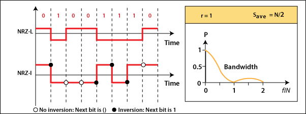
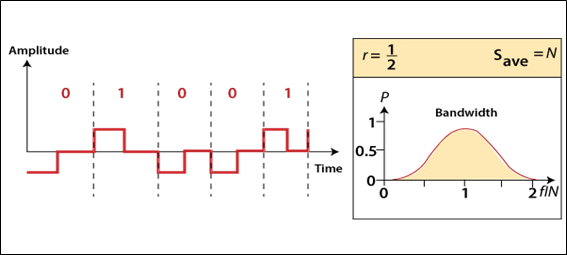
NRZ (Non-Return to Zero): There are two versions of NRZ in the polar schemes: NRZ-L and NRZ-I. NRZ-L stands for NRZ-Level. In the first version of NRZ, the value of the bit is determined by the level of the voltage. NRZ-I stands for NRZ-Invert. In the second version of NRZ, the value of the bit is determined by the change in the level of voltage. If there is no change in the value of the bit, then the bit is 0, and if there is a change in the value of the bit, then the bit is 1.
N/2 Bd is the average signal rate for both NRZ-L and NRZ-I. DC component problem is in both NRZ-L and NRZ-I.
RZ (Retune to Zero): The key issue with NRZ (Non-Return to Zero) encoding occurs when the clocks of the sender and receiver are not synchronized. The receiver does not know when one-bit finishes, and when the next bit begins. The RZ (return-to-zero) scheme is one solution, which uses three values: positive, negative, and zero. Positive voltage represents for 1, Negative voltage represents for 0, and Zero voltage for none.
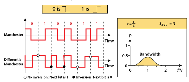
Biphase (Manchester and Differential Manchester)
Manchester scheme is a mixture of the RZ and NRZ-L scheme.
Differential Manchester scheme is a mixture of the RZ and NRZ-I scheme. Manchester and Differential Manchester is minimum bandwidth two times greater than the NRZ.
Bipolar Schemes
Bipolar scheme sometime is called the multilevel binary. The NRZ is an alternative to the bipolar scheme. It was developed in the later of NRZ.
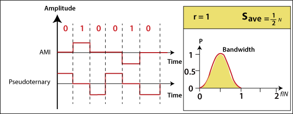
In this scheme, there are three voltage levels: +ve (positive), -ve (negative), and 0. At zero, it is one data element of the voltage level, while another component of the voltage level alternates between positive and negative. There are two variations of the bipolar scheme one of the AMI and another pseudoternary.
AMI and Pseudoternary: The full form of AMI is Alternate Mark Inversion, and it is a standard bipolar encoding scheme. Variations of AMI encoding is referred to as the Pseudoternary. Both the AMI and Pseudoternary are shown in the diagram below.
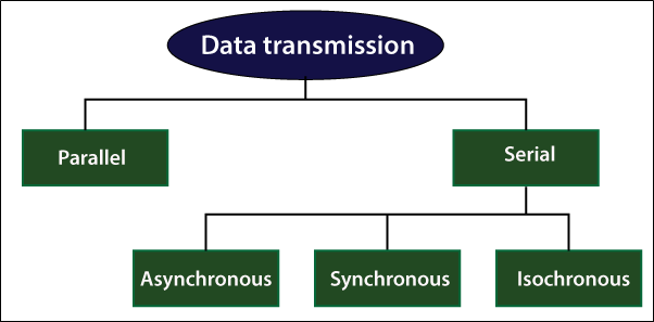
Transmission Modes
The transmission mode decides how to data is transferred between one device to another device. It can transfer the data to two different modes: Parallel and Serial. Types of the transmission mode are shown in the below diagram.
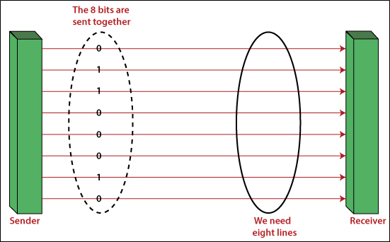
Parallel Transmission
In the Parallel transmission, n bits are sent by n communication lines at a time. If you want to send the n bits, then you will use the n lines. The main advantage of parallel transmission is the high-speed transfer of the data. The main disadvantage of parallel transmission is that it covers short distances. It is very expensive because the n communication lines transmit n bits of data. Parallel transmission is shown in the figure.
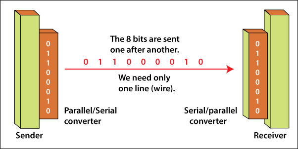
Serial Transmission
In Serial Transmission, n bits of data are transmitted one by one in the sequence. The serial transmission uses only one line to transmit the data between the sender and the receiver. It is used in the telephone lines. The main advantage of serial transmission is that it is very cheaper. The main disadvantage of serial transmission is that its speed is very low because the data is transmitted in the sequence. Serial transmission is shown in the figure.
Type of Serial Transmission
1. Asynchronous Serial Transmission
2. Synchronous Serial Transmission
3. Isochronous Serial Transmission
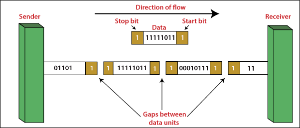
Asynchronous
In the asynchronous transmission, only one character is sent at a time, whether it is a number or alphabet. It sends a start bit at the beginning and sends one or more stop bits at the end of each byte, as shown in the diagram below.
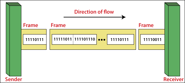
Synchronous
In the synchronous transmission, the data is sent in block format at a time, and each block has a lot of characters. It sends the bits one by one without any start or stops bits or gaps, as shown in the diagram below.
Isochronous
In the isochronous transmission, the data arrives at a fixed rate. Isochronous transmission is a mixture of the asynchronous and synchronous features.