Flow Control in Data Link Layer
The Data Link Layer is the second layer in the OSI Layered Model. With its intricate functions and obligations, this layer is the most complex. The data connection layer presents itself to the higher layer as the communication medium while concealing the specifics of the underlying technology.
The data connection layer operates between two hosts that are functionally connected in some way. The direct link could be broadcast or point-to-point. It is argued that systems on a network that broadcasts are on a single link. The data connection layer's activity becomes increasingly complex when numerous hosts are involved in a single collision domain.
Bit by bit, the data stream is converted to signal by the layer of data links and sent across the hardware underneath.
In the network architectural model of OSI (Open Systems Interconnection), the data link layer is the second layer from the bottom. It is in charge of transmitting information from one node to another. Its primary responsibility is to provide error-free information transfer. Additionally, encoding, decoding, and organizing data that comes in and leaves are under the purview of DLL. This OSI model layer is regarded as among the most sophisticated because it keeps all of the hardware's underlying complexity hidden from the other levels above.
Layers underneath the Data Link Layer
Two sub-layers comprise the information link layer, and they are as follows:
1. Logical Link Control
This data link layer's sublayer handles the data flow between apps and other offerings or multiplication; LLC must also provide error messages and acknowledgements.
2. Media Access Control (MAC)
The MAC sublayer governs tangible media access, device interface, and frame routing.
Features of the Data-Link Layer
The data link layer does A lot of work in preparation for the top layer. These are the following:
- Framing
The network layer packets are taken by the data-link layer and wrapped into frames. After that, it sends each frame to the computer's hardware bit by bit. The data link layer at the receiver's end gathers signals from the computer's components and puts them together into pictures.
- Addressing
The data-link layer provides the layer-2 hardware addressing technique. It is believed that each physical address on the link is unique. Equipment is encoded with it throughout the entire production process.
- Synchronization
The two devices must be in sync for the transfer of information whenever data frames are sent across the link.
- Error Control
Signals may occasionally experience transitional problems, flipping the bits. The errors are found, and a recovery effort is made.
Flow Control in Data Link Layer
Flow control is the method used to regulate the speed of data transfer between the sender and recipient in the data link layer. The receiver may become overloaded with the sender's frames if the sender uses a more powerful and fast computer than the recipient.
In this case, even if there are no errors in transmission, the receiving device could miss certain frames because it cannot process the data at the sender's delivery rate.
Additionally, before sending the information to its higher layers, the receiver must process the data it got from the person who sent it at its data link layer. The recipient designates a maximum-length data buffer to be used for storing the information that was sent back. After this buffer procedure, the receiver selects the data and sends it to the top layer.
If the flow control device is absent, the recipient's data buffer may eventually fill up and overrun since the datalink may be occupied with processing previously acquired data. The receiver may lose some of the data or frames delivered during this operation. There are two ways to handle flow control to solve this issue.
Methods of Flow Control
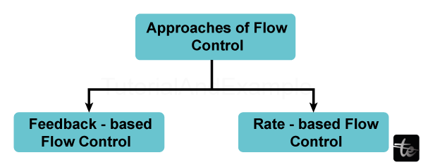
1 Feedback-Based Flow Control
When using feedback-based flow control, the sender receives feedback from the receiver indicating whether or not the receiver can process packets at the rate that the sender is sending them. To put it another way, the recipient's response lets them know how it is doing and allows it to send further data.
2. Rate based Flow control
The rate-based flow control method limits the speed at which the sender can send packets rather than allowing the recipient to offer input to the sender.
Flow Control in Data Link Layer
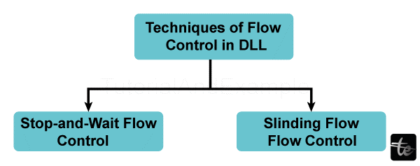
Stop and Wait Protocol
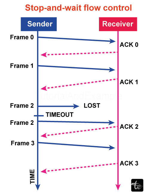
Because the stop-and-wait protocol is contact-oriented, a link must be made between the sender of the message and the recipient before any communication can occur. The sender closes the relationship after the conversation is finished.
In this scenario, the sender transmits a single data packet to the recipient and watches for an acknowledgement. It does not send another one until the sender receives an acknowledgement for the earlier message. By doing this, the protocol controls the flow so that the information packets don't overwhelm the receiver.
The timer for an information packet begins when the sender's computer transmits it to the recipient. The sender's computer resents that data packet if it fails to get an acknowledgement until the timer goes off.
Every data packet in the stop-and-wait protocol has a signature appended to it, which is validated at the receiving end. No acknowledgement is issued for the associated packet if it is malformed. As a result, the sender sent the data packet again after the period expired. Errors are managed by stop-and-wait in this way.
Advantages
- This approach is the most straightforward, and every frame is verified and accepted.
- This approach is also quite precise.
Disadvantages
- This approach is a little slow.
- A single frame or packet can only be sent at a time.
- It is incredibly ineffective and slows down the communication process
Sliding Window Protocol
The foundation of the sliding window protocol is pipelining, which allows a sender to broadcast numerous frames while awaiting an acknowledgement. There are two approaches to implementing the window-sliding protocol: the selective repeat protocol and the go-back-n protocol.
A sliding window is an imagined box surrounding frames that have either been transmitted by the sender or are about to be sent. Sliding window protocol uses a sequential frame numbering scheme that allows one to track the frame delivered by the sender's computer and accepted by the recipient.
Advantages
- It works much more effectively than the flow control, which stops and waits.
- This approach boosts productivity.
- It is possible to transmit many frames consecutively.
Disadvantages
- The transfer of several frames causes complexity for both the sender and the recipient, which is the fundamental problem.
- Data frames or packets may be sent out of schedule to the recipient.
- Only one packet can be sent at a time.
- Propagation delays are greater than delayed transmission when there is a significant distance between the sender and the recipient. Productivity would, therefore, drastically decline.
- The sender must wait for a response after each transfer, which delays communication duration.
a) Return to N
The person who sends the frame can send "n" frames in the go-back-n protocol before anticipating the first acknowledgement. Since N is the sender's window measurement, in this case, the sender sends a total of N frames while initially awaiting acknowledgement.
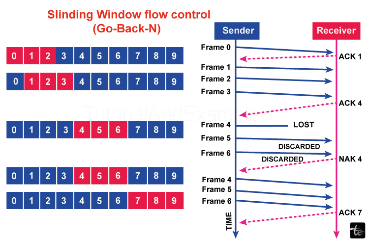
In the meantime, the sender pane slides by a few slots, covering the picture frames that can be sent following that, while the recipient begins transmitting an acknowledgement message.
If a frame is corrupted during transmission, lost, or fails to receive an acknowledgement, the sender's timer expires, and all images inside their current sliding window are retransmitted.
b)Selective Repeat Protocol
The selective repeat overcomes the go-back-n protocol's inefficiency. In go-back-n, all of the frames from that particular sender sliding window are retransmitted by the sender if it does not receive an acknowledgement. However, what happens if numerous frame losses or significant frame inaccuracies result in much bandwidth waste? Using selective repetition for the layer of data links flow control.
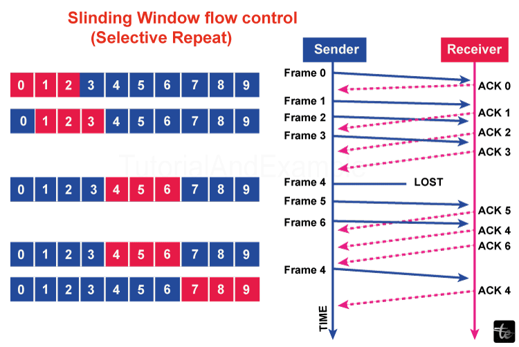
Only the portion of the frame the message's sender does not receive an acknowledgement for before the associated timer ends is transmitted in a selective repeat. Therefore, compared to go-back-n, the repeat approach is more effective.
This is how the data link controls flow and errors when the sender of the data and the recipient are corresponding.