Multiple Access Control
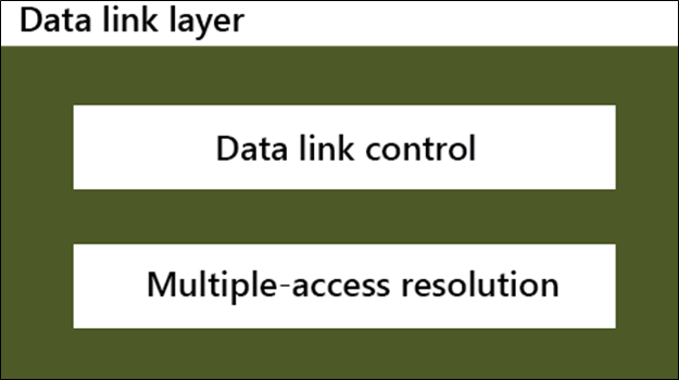
Multiple Access Control: The data link layer is separated into two sub-layers. The upper sub-layer is responsible for flow control and error control that is called the logical link control layer. The lower sub-layer is responsible for multiple access resolution that is called media access control (MAC). The Sub-layer of the data link layer is shown in the figure below.
The media access control protocol is divided into three protocols: The Random access, the Controlled-access, and the Channelization protocol.
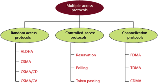
Random Access Protocol
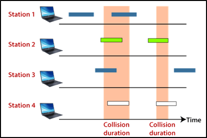
In the Random access protocol, all systems are equal. No anyone system can depend and control another system. However, if more than one station attempts to transmit the data, there is an access conflict—collision, due to which the frames are either lost or changed.
Random access protocol is divided into two categories; firstly, aloha, and second CSMA (carrier sense multiple access). CSMA is later further divided into two parallel methods; CSMA/CD and CSMA/CA. When a collision is detected, CSMA/CD tells the station what to do. CSMA/CA attempts to stop a collision.
1. Aloha
ALOHA is a Multiple Access Protocol which is used for random access in the network. Aloha was designed for the wireless local area network (WLAN), which is also known as the radio broadcast. In this method, any user can transmit the data at any time.
Type of Aloha
1. Pure Aloha
2. Slotted Aloha
Pure Aloha: Pure aloha is also called the original aloha protocol. It's a simple but elegant protocol, i.e., whenever the system has a data frame to send, it transmits the data frame continuously. Due to which the risk of collision is very high in this aloha method. Shown in below pure aloha.
- The maximum throughput occurs at G = 1/2, which is 18.4%.
- In Pure Aloha, the probability of successful transmission of the data frame is S= G* e^-2G
- In Pure Aloha, vulnerable time is: 2 * Tfr
Slotted Aloha: Slotted aloha was developed to improve the efficiency of the Pure Aloha. In this Aloha, the time of the systems is divided into slots so that the system can send only one frame to a slot, and this frame can only be sent at the beginning of the slot. If a system cannot send a frame at the beginning of the slot, then it has to wait for the next slot to start. If two systems try to transmit the frame at the beginning of a time slot. But it is better than pure Aloha because it has less chance of collision. Shown in below slotted aloha.
- In Slotted Aloha, maximum throughput occurs at G = 1, which is 37%.
- In Slotted Aloha, the probability of successful transmission of the data frame: S=G* e^-G
- In Slotted Aloha, vulnerable time is: Tfr
2. CSMA (Carrier Sense Multiple Access)
CSMA was developed to improve performance and minimize the chance of collision. Each station is required to test the state of the medium before transmission. In other words, CSMA is based on the principle “sense before transmit.” CSMA can reduce the risk of collision, but it cannot remove it.
CSMA primary access mode:
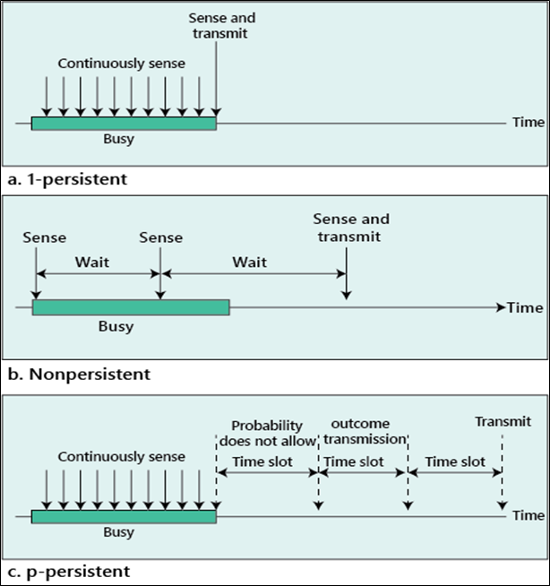
1-Persistent: The 1-persistent method is very easy and quick. In this method, after the station finds the line empty, it immediately transmits its frame. The chances of the collision are very high in this method because two or more stations immediately transmit their frames as soon as the line is found empty.
Non-Persistent: In the non-persistent method, if found the line is empty, it transmits the frames immediately. If the line isn't clear, it waits for a random period and detects the line again. This approach decreases the risk of a collision.
P-Persistent: This method is a combination of 1-Persistent and Non-Persistent advantages. The p-persistent approach decreases the risk of collision and increases performance.
In the P-Persistent approach, the following steps follow after the station finds the line-empty:
- With probability (p), the station transmits its frame.
- With probability (q = 1 ? p), the station waits for the starting of the next time slot and re-test the line.
- If the line is empty, it goes to step 1.
- If the line is not empty, it behaves as though a collision has happened, and it uses the back-off process.
In later, CSMA is divided into two parallel methods: CSMA/CD and CSMA/CA. When a collision is detected, CSMA/CD tells the station what to do, and CSMA/CA attempts to stop a collision.
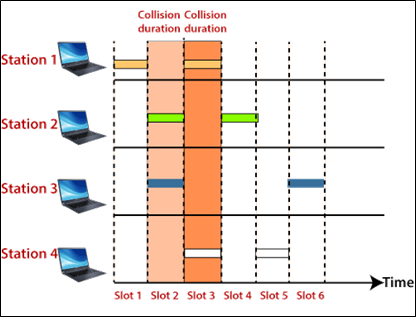
CSMA/CD (Carrier Sense Multiple Access with Collision Detection)
CSMA/CD is a carrier communication network protocol that operates in the Multiple Access Control layer.
In this approach, the station tracks the medium after transmitting a frame to see whether the transmission was successful or not. If so, the station work is completed. But, if there is a collision, the frame is re-sent.
CSMA/CA (Carrier Sense Multiple Access with Collision Avoidance)
CSMA/CA is used in wireless networks because CSMA cannot detect the collision, so CSMA/CA is the only solution to collision avoidance.
In CSMA/CA, Collisions are avoided by the use of three techniques:
- Interframe space
- Contention window
- Acknowledgment
- Interframe space: If a station detects the idle channel, the station does not send the frame immediately. It waits for a time period. That time period is called IFS time. IFS is often used to describe the station's priority.
- Contention window: The contention window is the sum of time that is split into slots. When a station is ready to send a frame, it can choose a random number of slots as the Wait time. According to the binary exponential back-off strategy, the number of slots in the window changes. There are shown in the figure below.
- Acknowledgment: Positive acknowledgment or time-out timer helps to guarantee a successful transmission.
Controlled Access
In this method, stations contact each other to see which channel is appropriate for transmission. A station may not send a frame until other stations approve it. There are three types of controlled access: Reservation, Polling, and Token Passing.
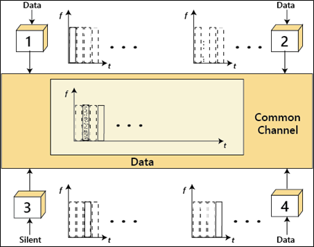
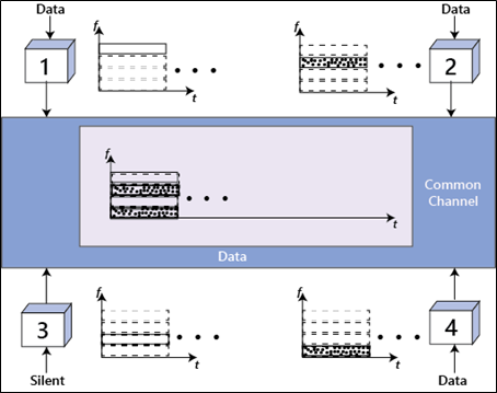
Channelization
In this process, the usable bandwidth of the network is shared between several stations in time, distance, or through-code. There are three types of Channelization: FDMA (Frequency Division Multiple Access), TDMA (Time Division Multiple Access), and CDMA (Code Division Multiple Access).
FDMA figure is shown below.
TDMA figure is shown below.