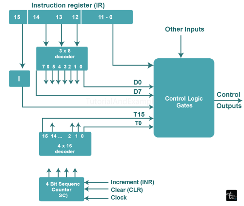
Block diagram of control unit
Introduction:
“Acontrol unit drives the associated processing hardware by creating a series of synchronised signals with the master clock.” The control unit's two main functions are instruction interpretation and instruction sequencing.
A control unit's primary role is to retrieve data from main memory, identify the devices and processes involved, and generate control signals to carry out the operations.
A control unit (CU) is an important part of a computer's central processor unit (CPU). Its principal job is to manage and coordinate the CPU's functions, which include instructions execution, data retrieval from memory, and management of input/output processes.

Control Unit Types
The following are the two types of control organisations:
Control Is Hardwired
The control logic of a hardwired organisation is implemented using gates, flip-flops, decoders, and other digital circuits. It can be optimised for a faster manner of operation. Control data is maintained in the control memory of a micro-programmed organisation.
The control memory is set to begin the required series of micro-operations. If the design to be amended or changed, the wiring between the various pieces of a hardwired control must be adjusted.
The control unit's block diagram is shown in the picture. It has two decoders, a sequence counter, and a number of control logic gates.
Some instructions retrieved from memory are stored in the Instruction Register (IR). As a result, the IR is separated into three elements: I bit, opcode, and bits 0 through 11. The opcodes are decoded using a 3 * 8 decoder, the outputs of which are represented by the symbols D0 through D7.
The subscripted number in the symbol represents the binary value of the particular opcode. The 15th bit of the instruction, symbol I, is transferred to a flip flop. The control logic gates contain bits that range from 0 to 11.
The sequence counter is a 4-bit binary counter that counts from 0 to 15. It can be synchronously increased or cleared. The timing signals T0 through T15 are the decoder's decoded outputs.
Control via microprogramming
The control memory is where the microprogrammed control saves its control data. The control memory is programmed, so it may begin the essential set of micro-operations. A microprogrammed control's alterations and adjustments can be accomplished by updating the microprogram in the control memory.
The control is claimed to be a Read-Only Memory (ROM), in which all control data is permanently recorded. The address of the microinstruction is supported by ROM. The control data register, on the other hand, stores the microinstruction retrieved from memory. It contains a control word containing one or more microoperations for the data processor.
During this procedure, the following address should be examined. The next address generator evaluates it. As a result, it is moved to the control address register for reading. The microprogram sequencer is the address generator that generates the next address. The address of the next microinstruction is determined by the sequencer's inputs. Different ways can be used to determine microinstructions.
Benefits of control unit block diagram:
here are various benefits to using a block diagram to illustrate a control unit in a computer system:
- visible Representation: Block diagrams depict the components and their linkages inside the control unit in a clear and visible manner. This facilitates the understanding of the system's architecture by designers, engineers, and students.
- The block diagram divides the control unit into discrete functional blocks or modules. Because of this modularity, it is easy to develop, analyse, and debug each component individually, allowing for easier maintenance and updates.
- Abstraction simple: It gives a simple abstraction of sophisticated hardware components. This abstraction lets designers to concentrate on high-level functionality rather than the specifics of individual gates, flip-flops, or transistors.
- Communication Tool: Block diagrams are a powerful tool for communicating with designers, engineers, and stakeholders. They can immediately comprehend the design and operation of the system, allowing for greater collaboration and decision-making.
- Debugging and troubleshooting: When a system faces problems, a block diagram aids in determining which individual block or module is to blame. It speeds up the process of debugging and troubleshooting.
- Documentation: Block diagrams are useful for documenting the design and development processes. They give a clear record of the system's design, enabling future teams' understanding and interaction with the system easier.
- Scaling: It enables easy system scaling and customization. Designers can identify the impacted blocks and make the appropriate changes if extra functionality or features are required