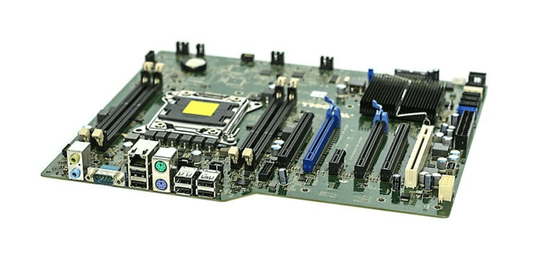
What is Motherboard?
The motherboard, also known as the mainboard or the baseboard, which is responsible for performing all the basic tasks on the computer. In mac, the motherboard is known as the logic board. It is the biggest integrated circuit located in the system. It is a printed circuit that forms the foundation of the computer. It supplies power to all the system components and facilitates communication between the various components of the system. All the components responsible for processing are connected to the system's motherboard. It is connected to the CPU, RAM, and ROM of the system. It has additional USB and PCI ports and is responsible for the communication between the CPU, RAM, as well as other system hardware components.
The motherboard is located in the system's Central Processing Unit, as the CPU comes in different sizes. The motherboard also comes in various shapes and sizes. There are various types of motherboards, allowing them to work with specific types of processors though they work with almost every hard disk.
The integrated circuit includes various chipsets that manage the system's keyboard, mouse, and storage. It acts as a control centre for the various I/O devices. Constant advancements are made in the motherboard chipsets; with every new chipset installed in the motherboard, the processing speed and efficiency of the motherboard increase. New components are also developed to work effectively with the new chipsets.
The first-time board of circuits of used in the IBM system. They called the circuit board the planar instead of the motherboard.
History of Motherboard
1981: Printed circuit board was developed for the IBM computer; they called the board planar instead of the word motherboard.
1984: IBM launched the full AT motherboard form factor in the factor. It required a very large place to set up and increase the system's size.
1985: A year later, the Baby AT motherboard was launched by IBM. Changes were made to reduce the size of the full AT motherboard.
1987: LPX motherboard was developed by Western Digital.
1995: Intel launched the first motherboard with ATX specifications in the market.
1997: In March, IBM, along with DEC, developed the NLX motherboard. By November, FIC and Intel built the motherboard that supported AGP. In December, Intel launched a micro-sized motherboard with ATX specifications.
1998: The first WTX motherboard form factor was introduced by Intel.
1999: Flex ATX motherboard form factor was developed by Intel.
2000: Kontron introduced the first motherboard with ETX specifications.
2001: UTX motherboard was developed by TQ-Components. In November, VIA technologies reduced the size of the ITX form factor and launched a Mini-ITX form factor.
2003: It was the first time a PCI slot was provided in the motherboard. In March, the size of the ITX form factor was further reduced, and the Nano-ITX was launched.
2004: To provide a better display, NVIDIA launched the motherboard that allowed the users to connect two video cards to the motherboard simultaneously. This year, Intel launched the motherboard that supported BTX specifications. The company also released the micro-BTX and Pico-BTX form factors in the market. In March, the first Mobile-ITX factor motherboard was released.
2005: PICMG launched the COM Express form factor. The motherboard with XTX form factor and specification motherboard was launched.
2006: The first motherboard specifically designed to play high graphic games was launched. A micro-ATX motherboard enabled the user to connect two video cards. This year, Supermicro launched the SWTX motherboard form factor in the market.
2007: Pico-ITX motherboard was launched, and AMD also developed the DTX form factor and the Mini-DTX form factor that increased the system's efficiency.
2010: The HPTX form factor was developed by the EVGA.
Components of a Motherboard
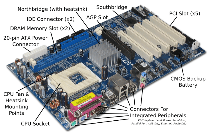
Despite the small size of the motherboard, it is equipped with numerous smaller components that allow it to perform its various functions. Its components include:
Heat Sink: Various components in the motherboard constantly generates heat. The heat sink is equipped with fans. The function of the heat sink and the fan is to maintain a constant temperature of these components. It is made up of metal alloys.
There are two types of heat sinks:
- Active Heat Sink: They are equipped with fans.
- Passive Heat Sink: These devices do not have any fans.
They act as the cooling devices for the processors and other components attached to the motherboard. It is used to refrigerate components such as video card processors and GPUs.
Parallel Port: These ports were available in the older model of motherboards. They were specifically provided to connect old printers. It requires different wires to send and receive bits of data, while the serial port only requires a single wire to both send and receive the data bits.
Back Pane Connectors: The user can establish a connection between the connector and the plug into the port. It is necessary to attach the connector of the I/O devices in the port to connect them to the system.
Capacitor: This device allows the user to store electrical charge in it. It is used to perform the function of a condenser. It prevents the Direct current from entering the motherboard component and allows only alternate current to pass through it. Whenever DC is supplied to it, it is converted into positive and negative charges on the opposite walls of the capacitor and converts Direct current into AC.
Northbridge: It is an IC chip located inside the motherboard and used to establish the connection between the CPU and the memory. It is directly connected to these components of the motherboard. The main function of the northbridge is to establish the connection between peripheral devices and the CPU.
Southbridge: This is not directly connected to the I/O devices, but it acts as a controller for the various hardware devices connected to the system. This whole IC chip is manufactured separately and is a different motherboard component.
Jumper: The function of the jumper is to break an electrical connection. It is a metal connector; the electric current can pass to certain parts of the motherboard while blocking it to some parts. It constitutes of small pin enclosed inside a jumper block. It works similarly to the inline switch and is responsible for controlling the electric circuit board.
Integrated Circuit: This chip is responsible for providing functionality to the motherboard. It acts as a microprocessor, amplifier, and even the oscillator. It can also store a minimal amount of data. It constitutes numerous logic gates and pathways that determine the flow of an operation.
Geoffrey Dummer was a British engineer who introduced the concepts of integrated circuits, but Jack Kilby and Robert Noyce developed the first IC. This component is used in almost all modern devices and is responsible for significantly reducing the system's size.
PCI slot: These slots were introduced in the motherboard to provide the option of adding extra internal components to the motherboard if needed. Intel released this design. It allows the user to connect additional peripheral devices to the motherboard, such as a modem, graphic cards, etc. They can enhance the performance of the system.
Memory Slot: This slot is reserved for connecting the system's Random Access Memory. The motherboard can have two to three of these slots. We can insert the RAM into the CPU using these slots and increase processing speed by increasing them. There are several types of RAMs available in the market, depending upon the speed and size of the RAM. Each slot allows only a specific type of RAM to get inserted into it.
USB Headers: Several small pins provide additional USB ports to connect devices with USB-type connectors to the system. These devices include a mouse, keyboard, etc.
Serial port Connector: This port only allows sending or receiving one-bit data at a time. It has only one wire used for both transmitting and receiving the data on the system. In Some systems (mostly compatible with IBM), these ports can serve communication purposes. Example: The user can connect to a modem using COM port1; not all devices can be connected to these ports.
Super I/O: This component was developed in the 1980s. It was first introduced as an expansion card and is responsible for controlling the working of less complex I/O devices such as Floppy Disk, Game ports, Infrared, etc. They are integrated chips embedded in the motherboards of a system to provide a common interface for multiple low bandwidth devices.
SATA: The parallel AT attachment equipped in the systems that were compatible with IBM, this connection's first version that was SATA 1.0, was introduced in 2001 to replace the above connections. SATA stands for Serial AT attachment. It significantly increased the performance and speed of accessing and working with drives. When used with a disk array, it delivered almost 1.5Gbps of performance to each drive of the array. A small cable is attached to the Serial AT attachment, which makes it easier to efficiently perform cable routing. It ensures better airflow than the cables that were previously used. Thus, the equipment does not get heated much.
System Panel Connectors: This panel forms the front panel of the system's central processing unit. It is responsible for performing all the functions that can be performed directly from the CPU console. It constitutes a reset button, a power button, and several LEDs. It also has key locks and case speakers. There are several types of cables connected to the motherboard; that includes PLED, Reset SW, PLED, etc. The connection is established using two different color wires that enable the user to determine which cable will be connected to which port.
Motherboard Form Factors
The motherboard form factor specifies the size of the motherboard. This determines the physical structure of the motherboard. The physical layout of the motherboard also determines the power supply required by the system. It is necessary to know the motherboard form factor to ensure compatibility between the motherboard and the peripheral devices. When constructing a system, it is necessary to know the layout of different components of the motherboard and the positioning of the mounting holes to align the equipment accordingly. The most common form factor is ATX. Over time, multiple form factors are developed. Let us discuss each form factor individually.
AT & Baby AT: It was before 1997 when the size of the motherboard was quite large. IBM manufactured these large motherboards. IBM used advanced technology to reduce the dimension of the motherboard. It was able to develop the AT form factor in 1984, and because of its smaller size, this factor became quite popular. Now, this form factor is also outdated. The advanced form factors such as ATX and Baby AT are more commonly used. BAT or Baby AT was introduced to replace the AT factor by IBM only. The size of the AT form factor was further reduced, and the compatibility with peripheral devices was enhanced. It was used with Pentium computers till the 1990s and was replaced with more advanced form factors.
ATX or Advanced Technology Extended: This form factor was developed by Intel and launched in 1995. This form factor was introduced to standardize the motherboard's design and build a basic layout the motherboard. Different versions of the ATX form factor were released in the market. Though they were not as popular as the BAT form factor, minor upgrades were performed in the ATX form factor, such as it came with a 20-pin connector to connect with the power supply. It ensured that the overlap was reduced between the motherboard and drive. They also soldered the ports for I/O devices directly on the motherboard.
BTX: It refers to Balanced Technology Extended. This was introduced as a replacement for the ATX. It was launched in 2004 by Intel. The new form factor included many features, such as it provides support to the components with high masses. The layout was improvised to facilitate cooling. This form factor was designed in such a way that the functionality of the motherboard could be extended further. It was equipped with PCI Express and USB 2.0. It had an inline airflow, allowing the user to change the position of memory and expansion slots. This also reduced the need for a fan in the system, thus reducing its noise. Despite introducing all these features, the company terminated its production by 2006. It was discontinued because the design of BTX was not based on the ATX form factor. When designing the form factor of the motherboard, the ATX is considered the standard form factor. The new advanced form factors are based on the legacy AT systems. Thus, BTX was incompatible with AT. It was not a piece of standard equipment for the industry.
DTX: It refers to discontinuous transmission. It was introduced to enhance two-way wireless communication. The efficiency was improved by allowing the system to mute the wireless telephone for a moment. The discontinuous transmission was developed by AMD in 2007. It was a variation on the ATX. This form factor was quite small and was specifically designed for personal computers. This motherboard form factor was compatible with ATX specifications, and AMD declared it as the standard form factor. Various smaller DTX was also launched in the market, such as Mini-DTX. The width of the printing circuit was reduced by removing layers from it. This also reduced the manufacturing cost and was selected as a standard while constructing small PCs. This design was called the Shuttle SFF design.
LPX: It stands for Low Profile Extension. This form factor was launched by Western Digital and became quite popular. It was used in most systems that were manufactured in the 1980s. It provided multiple ports to establish video, parallel or serial connections with the system. It also enabled the user to connect an expansion card parallel to the motherboard. The manufacturer provided an extra slot for a riser card; therefore, it is known as a Low Profile Extension. The system's design was sleeker compared to systems equipped with the Baby AT form factor.
microATX: This provided all the features introduced in the ATX form factor. They reduce the size of the form factor. The new design saved space and reduced the manufacturing cost as it required less material. They reduced the length and width of the motherboard. Intel developed it in 1997. They can be used in any system that supports the ATX form factor. They are also used in any system with a smaller size. The reduced size of the motherboard provides more space for the input and output devices in the back. These form factors were equipped with integrated I/O connectors that reduced the emission caused by the motherboard.
NLX: It refers to New Low Profile Extended. This form factor is based on the board. It was developed by Intel and was released on the market in 1997. They were developed to standardize the design of the LPX form factor. They can be easily removed from the system. It provided support for various connections such as USB, DIMM, and AGP. It allows the user to use larger modules and reduces the cable's length. Unlike the Low profile Extended, this form factor was launched as a standard, which provided the same feature but did not have a standard layout. It also provided multiple options to connect various components. It can be used for the repair and upgrade of the components.
Number of Ports on the Motherboard
There is no exact number that can be placed on the motherboard. There is no clear answer to how many ports are to be provided on the motherboard? The developer can determine the number of ports required by referring to the documentation of the form factor. It can be determined by reading the specifications of the motherboard. In case the documentation is not available, the pdf file of the documentation can be downloaded from the manufacturer's website. They are free to download.
Connecting the Motherboard to the System
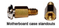
We can place the motherboard in the computer case using standouts. Once the motherboard is attached to the computer case, the computer components of the CPU are connected to expansion cards or the motherboard of the system.
Standout: They are similar to screws; they are made up of metals or plastic and can be attached to the computer case. It provides the necessary support to the motherboard. They prevent the motherboard from touching the metallic surface of the case. The motherboard consists of integrated circuits, and electrical signals are continuously transmitted in the motherboard. If the motherboard and the metal case come in contact, it can damage the motherboard's components. Thus, it is always preferred to attach the motherboard using these standouts.